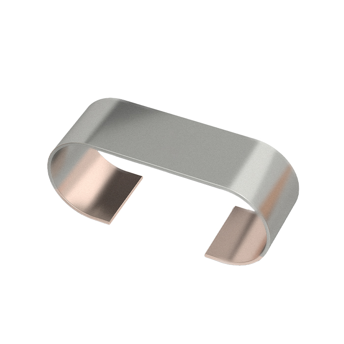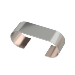
ASHP-K SERIES

✔️ Application Scenario
ASHP-K alloy shunts are ideal for BMS, EV traction inverters, and industrial drives, delivering ultra-stable current sensing from -65℃ to +170℃.
✔️ R&D Technology
Featuring Karma alloy and electron-beam welding, ASHP-K achieves ultra-low TCR down to ±10ppm/℃, ensuring high precision over a wide temperature range.
✔️ Production Strength
Fully automated production lines and 100% electrical testing ensure consistent quality, with annual capacity exceeding 200 million pieces.
✔️ Stock Availability
ASHP-K standard values (1mΩ, 2mΩ, 3mΩ) are in stock now, available in 2000/2500pcs per reel for fast global delivery.
✔️ Cooperation Case
A top European EV manufacturer adopted ASHP-K 3920 for battery pack current sensing, achieving ±0.5% accuracy and zero failures after 3000 thermal cycles.
APPROVAL SHEET
ASHP-K SERIES
Alloy Shunt
Version | Date | Description of amendment | Draft | Checked |
A1.0 | 20-Dec.-2022 | First issue | Jiamiao Wang | Ziyang Hu |
A1.1 | 16-Jan.-2024 | Increase the partial resistance | Jiamiao Wang | Ziyang Hu |
A1.2 | 18-Mar.-2024 | 1、Adjust the pin length (A) dimensions of the 5930 package product and the corresponding recommended PCB layout (a) dimensions, 2、Add product (B) size description.
| Jiamiao Wang | Ziyang Hu |
A1.3 | 15-Sep.-2025 | 1、Delete the 2512 package. 2、Modify the technical parameter data 3、Revise the content of the durability test
| Zhijun Jiang | Xiaohui Deng |
1.Product Description
Product name:ASHP-K series
Description:ASHP-K series Alloy Shunt provide precise current sensing with low TCR and high power, ideal for automotive and industrial applications.
1.1 Part Number Explanation
The part number of the high power precision resistor is identified by the type name, Resistance Alloy, tolerance,TCR,Dimension and resistance value.
Example: ASHP-K-5-1F-L
Type | Resistance Alloy | Dimension | Resistance Value | Tolerance | TCR |
ASHP | K=Karma | 5=3920 7=5930 Unit:in | 1 Unit:mΩ |
D=±0.5% F=±1% G=±2% J=±5%
| L=±10 P=±20 Q=±30 Unit:ppm/℃
|
(1) Type name: ASHP series
(2) Resistance Alloy:K=Karma
(3) Dimension:5=3920;7=5930
(4) Resistance:1
(5) Tolerance:D=±0.5%;F=±1%;G=±2%;J=±5%
(6) TCR:L=±10;P=±20;Q=±30
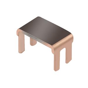
1.2 Products Dimension


Type | Size (in) | W | A | C | B | H |
ASHP-K | 3920 | 10.0±0.2 | 2.0±0.3 | 5.2±0.3 | 6.0±0.2 | 0.3-0/+0.3 |
5930 | 15.0±0.3 | 4.3±0.3 | 7.6±0.4 | 6.4±0.2 | 0.3-0/+0.3 |
1.3 PCB-layout (Reflow-soldering)

Solder pad type | w | c | a | b |
ASHP-K-3920 | 11 | 6 | 2.7 | 5.6 |
ASHP-K-5930 | 16 | 8.5 | 5 | 6 |
2. Technical Data
Size | Resistance Alloy | Resistance Range(mΩ) | Resistance Value(mΩ) | D±0.1 (mm) | *TCR | P70 °C |
3920 | K | 1~4 | 1 | 1.7 | ±10 | 9 |
±20 | ||||||
±30 | ||||||
2 | 1 | ±10 | 7 | |||
±20 | ||||||
3 | 0.8 | ±10 | 6 | |||
±20 | ||||||
4 | 0.8 | ±20 | 5 | |||
5930 | 0.8~3 | 0.8 | 1.7 | ±30 | 10 | |
1 | 1.4 | ±20 | 9 | |||
±30 | ||||||
2 | 1.0 | ±20 | 8 | |||
3 | 0.8 | ±20 | 7 |
TCR(ppm/℃):Test was conducted with the temperature from -20℃ to 120℃ , while 20℃ worked as reference.
Note: Unless the resistance value is specified, the temperature drift can generally reach ±20ppm.
3. Endurance Test
Iterms | Additional Requirements | Reference | Limits |
High Temperature Exposure | 1000 hrs. (T=170°C) , unpowered. Measurement at 24±4 hoursafter test conclusion . | MIL-STD-202 Method 108 | ±0.5% |
Temperature Cycling | 1000 Cycles(-55°C to +150°C) , unpowered. Minimum dwell time 15min. at each temperature extreme.maximum transition time1 min. . Measurement atleast 24hoursafter test conclusion . | JESD22-A-104 | ±0.5% |
HumidityBias | 1000hrs. (85℃/85%RH) . Note: Specify conditions: 10% of operating power.Measurement at 24±4 hoursafter test conclusion . | MIL-STD-202 Method 103 | ±0.5% |
High Temperature Operating Life | 1000 hrs.(T=125°C). Rate power was applied to the products intermittently: 90 minutes ON and 30 minutes OFF . Measurement at 24±4 hoursafter test conclusion . | MIL-STD-202 Method 108 | ±0.5% |
Resistance to Soldering Heat | 250℃±5℃ , 30s±5s | MIL-STD-202 Method 210 | ±0.5% |
Solderability | Weld bath temperature 245°C±5°C, duration5±0.5S . | J-STD-002 | 95% Coverage Minimum |
Vibration | 20 min.(5 g's) , test from10Hz-2000 Hz, 12 cycles each of 3 orientations . | MIL-STD-202 Method 204 | ±0.5% |
Board Flex Test | Apply an external force once to the circuit board, bend at least Dx = 2mm, duration 60+5 S . | AEC-Q200-005 | ±0.5% |
Terminal Strength (SMD) | Apply an external force once to the side of the test device, the force is 17.7N (1.8kg), duration 60+1S . | AEC-Q200-006 | ±0.5% |
Mechanical Shock | 1) Pulse waveform: Half-Sine pulse; 2) Accelerate peak: 100g's; 3) Pulse duration: 6ms; 4) Orientation & Shock time: ±X, ±Y, ±Z, 3 times each orientation, total 18 times . | MIL-STD-202H Method 213 | ±0.5% |
ESD | 1) Direct Contact (DC): ±6kV ; 2) Air Discharge (AD): ±12kV, ±16kV, ±25kV . | AEC-Q200-002 REV-B | ±0.5% |
Flame Retardance | 1) Test current: 100%, 115%, 130%, 150% (Rate current) ; 2) Test duration: 1h . | AEC-Q200-001 | The following constitutes a failure: 1)A flame over 3.0 seconds duration; 2)An explosion: 3) A temperature above 350'c sustained for over 10 seconds. |
4.Power Derating Curve

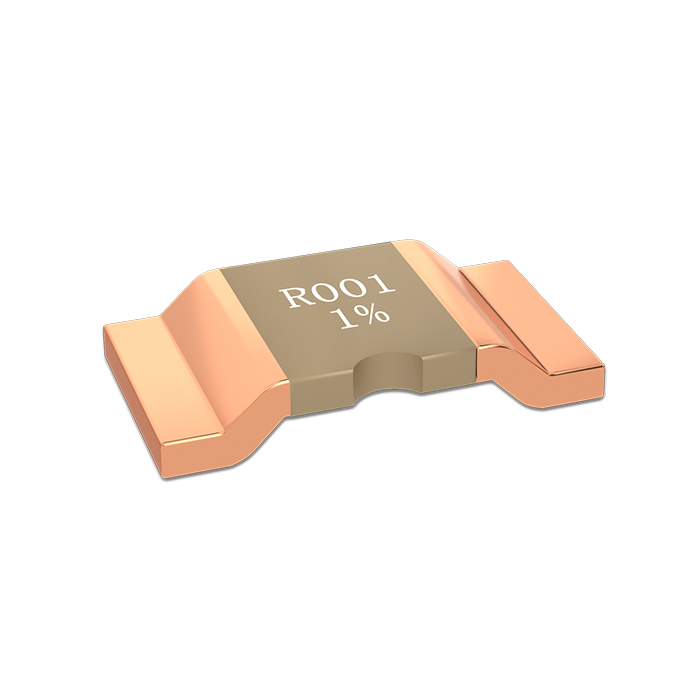
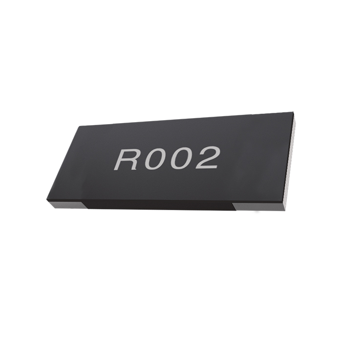
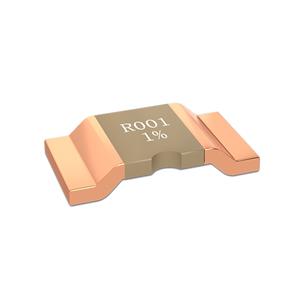
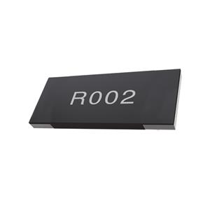
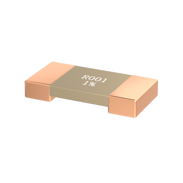
5.Marking
Mark | Explanation |
R001 1% | R001:1mΩ (Value阻值) 1%:±1% (Tolerance精度) |
0m80 0.5% | 0m80:0.8mΩ (Value阻值) 0.5% :±0.5% (Tolerance精度) |
6.Packing

Unit/mm
Size | A±0.15 | B±0.15 | W±0.3 | E±0.1 | F±0.1 | P0±0.1 | P1±0.1 | P2±0.1 | D0±0.1 | T±0.2 | Quantity (pcs) |
3920 | 5.7 | 10.5 | 24 | 1.75 | 11.5 | 2 | 4 | 12 | 1.50 | It depends on the height of the product D size. | 2500 |
5930 | 8.1 | 15.5 | 24 | 1.75 | 11.5 | 2 | 4 | 12 | 1.50 | 2000 |
Size | 3920 | 5930 |
φA | 330 | 330 |
φB | 100 | 100 |
φC | 13 | 13 |
W | 24.5 | 24.5 |
T | 29 | 29 |

This document is a product specification. Contents are subject to change without notice.
© 2026 THUNDER PRECISION RESISTOR CO.,LTD. All Rights Reserved.