YLR SERIES

✔️ Application Scenario
YLR series current sensing resistors are widely used in BMS, automotive electronics, and power supplies, offering stable performance from -65℃ to +170℃.
✔️ Cooperation Case
A global EV manufacturer selected YLR series for battery pack current sampling, achieving ±0.5% tolerance and reliable operation over 2000 thermal cycles.
✔️ R&D Technology
With electron-beam welded construction and CuMnSn/Karma alloy, YLR series achieves low TCR down to ±50ppm/℃, ensuring high precision for current sensing.
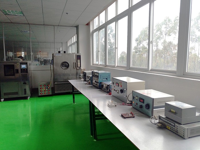
✔️ Production Strength
Fully automated lines and 100% electrical testing ensure consistent quality of YLR series resistors, supporting annual output exceeding 500 million pieces.
✔️ Sales Volume
YLR series has shipped over 300 million units worldwide, trusted by automotive and industrial customers for stable performance and fast delivery.
✔️ Stock Availability
YLR series standard values (1mΩ, 10mΩ, 50mΩ) are in stock now with 3000pcs/reel, ready for immediate global shipment.
APPROVAL SHEET
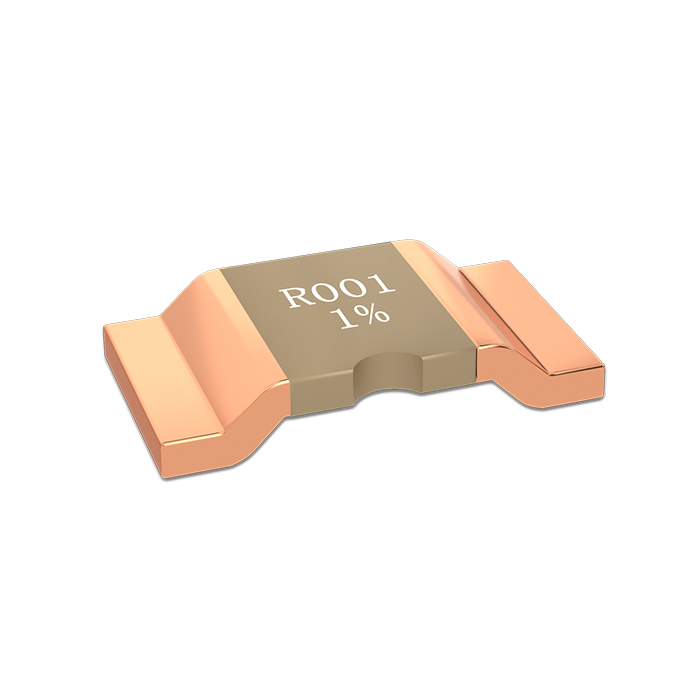
YLR SERIES
Low Resistance Metal Strip Chip Resistors
Version | Date | Description of amendment | Draft | Checked |
A2.0 | 28-Mar-2024 | First edition release | 蒋林帆 | 王磊 |
A2.1 | 16-Apr-2024 | Add the-Y suffix to represent white text | 蒋林帆 | 王磊 |
A2.2 | 11-May-2024 | Update tape size parameters | 蒋林帆 | 王磊 |
A2.3 | 16-Aug-2024 | Adjustment of Pulse Curve Diagram Clarity with Model Suffix Description | 蒋林帆 | 王磊 |
A2.4 | 11-Nov-2024 | Correction of resistance range for 1206 and 2010 package sizes | 蒋林帆 | 王磊 |
A2.5 | 26-Mar-2025 | Correction of English Writing of CuMn and Reflow Soldering Curve | 余凤玲 | 王磊 |
A2.6 | 26-Nov-2025 | YLR06 Carrier size modification: The width of A has been changed from 2.1±0.1mm to 1.9±0.1 mm, and the length of B has been changed from 3.6±0.1mm to 3.4±0.1 mm. | 鲁伟 | 程子鹏 |
1.Product Description
Product name:YLR series
Description:YLR series alloy chip resistors provide precise current sensing with low TCR and high power, ideal for automotive and industrial applications.
1.1 Part Number Explanation
The part number of the high power precision resistor is identified by the type name, power, Other,tolerance, size and resistance value.
Example: YLR12-3-10F
Type | Size | Power | Resistance | Tolerance | Other |
YLR | 06=1206 10=2010 12=2512 17=2817 28=2728 37=3637
| 3=3W | 10=10mΩ |
D=±0.5% F=±1% G=±2% J=±5%
| Blank=Laser marking -Y=Printed marking |
(1) Type name: YLR series
(2) Size:06=1206;12=2512
(3) Power Rating:1=1W;2=2W;3=3W
(4) Resistance:1=1mΩ;10=10mΩ;0=0mΩ
(5) Tolerance:D=±0.5%;F=±1%;G=±2%;J=±5%;Z=0mΩ
(6) Other:Blank=Laser marking;-Y=Printed marking
1.2 Products & Recommend Pad Dimension


Unit/mm
Type | Resistance(mΩ) | W±0.2 | C±0.2 | A±0.2 | D±0.1 | L | a | c |
YLR06 | 2~10 | 3.2 | 1.6 | 0.6 | 0.8 | 1.6 | 1.7 | 1.8 |
YLR10 | 2~30 | 5 | 2.5 | 0.6 | 0.8 | 3.6 | 1.5 | 3.5 |
YLR12 | 0.5~0.9 | 6.35 | 3.2 | 2.3 | 0.8 | 1.5 | 3.4 | 4 |
1 | 0.9 | 1.0 | 4.1 | 2.1 | ||||
2~50 | 0.9 | 0.8 | 4.1 | 2.1 | ||||
YLR17 | 1~50 | 7.1 | 4.3 | 1.2 | 0.8 | 3.5 | 2.7 | 5.2 |
YLR28 | 1 | 6.8 | 7.2 | 1.2 | 1.0 | 4.5 | 3.0 | 7.8 |
2~50 | 0.8 | |||||||
YLR37 | 1~50 | 9.14 | 9.4 | 2.2 | 0.8 | 4.5 | 3.0 | 9.9 |
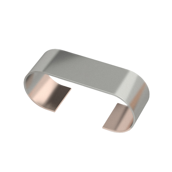
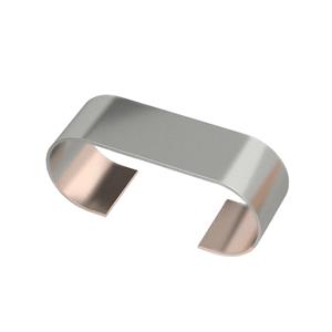
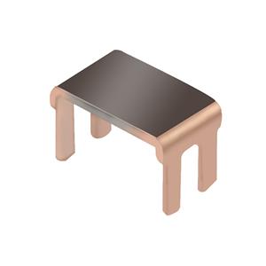
1.3 Item Construction
Electron-beam welded constructions

2. Standard Electrical Specifications
Type | Size | Rated Power(W) | Material | Resistance /mΩ | TCR① (ppm/℃) | Resistance Tolerance (%) | Operating Temperature |
P70℃ | |||||||
YLR | 1206 | 2 | CuMnSn CuMn Karma | *2~10 | ±50 | ±0.5% ±1% ±2% ±5% | -65℃~170℃ |
1 | 2~10 | ||||||
2010 | 2 | 2~30 | ±50 | ||||
2512 | 3 | 0.5~0.9* | ±75 | ||||
1~50 | ±50 | ||||||
2 | 0.5~0.9* | ±75 | |||||
±50 | |||||||
1~50 | |||||||
2817 | 5 | 1~50 | |||||
±50 | |||||||
3 | 1~50 | ±50 | |||||
2728 | 5 | 1~50 | ±50 | ||||
4 | 1~50 | ±50 | |||||
3637 | 5 | 1~50 | ±50 | ||||
3 | 1~50 | ±50 |
* Short Time Overload were tested with 2.5×Rated power for 10 s
① TCR(ppm/℃):Test was conducted from 20℃ to 120℃ while 20℃ worked as the reference.
3. Endurance Test
Items | Additional Requirements | Reference | Limits |
Temperature Cycling | 1000 Cycles (-55℃ to +150℃) | JESD22 Method JA-104 | ±0.5% |
ESD Test | 1) Direct Contact (DC): ±6kV; 2) Air Discharge (AD): ±12kV, ±16kV, ±25kV; | AEC-Q200 REV D June 1 | ±0.5% |
High Temperature Exposure | 1000hrs.@T=170℃.Unpowered. | MIL-STD-202 Method 108 | ±0.5% |
Moisture Resistance | t=24hrs/cycle.Note: Steps 7a & 7b not required. Unpowered. | MIL-STD-202 Method 106 | ±0.5% |
Biased Humidity | 1000hrs 85℃/85%RH。Note: Specified conditions:10% of operating power. | MIL-STD-202 Method 103 | ±0.5% |
Operational Life | Condition D Steady State TA=125℃ at rated power. | MIL-STD-202 Method 108 | ±0.5% |
Thermal Shock | 1000X(-55°C to +150°C) | MIL-STD-202Method107G | ±0.5% |
Solderability | 235℃±5℃,2s±0.5s | J-STD-202 | 95% Coverage Minimum |
Resistance to Soldering Heat | 260℃±5℃,10s±1s | MIL-STD-202 Method 210 | ±0.5% |
Short Time Overload | 5×Rated power for 5 s | MIL-STD-202 Method 201 | ±0.5% |
Shock | 100g , 6ms , Orientation & Shock time: ±X, ±Y, ±Z; 3 times each orientation, total 18 times. | MIL-STD-202 Method 213 | ±0.5% |
Vibration | 5 g's for 20 min, 12 cycles each of 3 orientations. Note: Use 8"X5" PCB .031" thick 7 secure points on one long side and 2 secure points at corners of opposite sides. Parts mounted within 2" from any secure point. Test from 10-2000 Hz. | MIL-STD-202Method204 | ±0.5% |
4.Solder Reflow Temperature Condition

5.Power Derating Curve

6.Pulse Capability Curve


7.Pulse Capability Curve


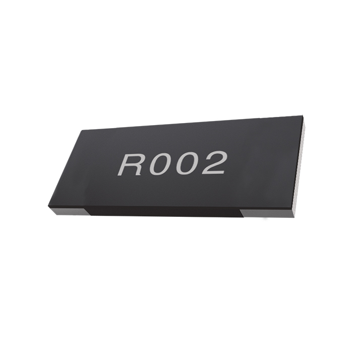
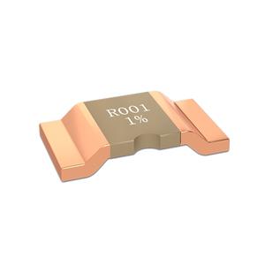
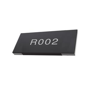
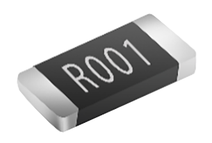
8.Marking
Laser Marking(No suffix) / White Printed Marking(With suffix "-Y"):
· All the products marking are 3 or 4 digits. ‘R’ designates the decimal location in ohms
E.g., :
· 3mΩ= R003; 50mΩ=R050;1.5mΩ=1m50
· 1206 series:3mΩ= 003; 15mΩ=015;1.5mΩ=1m5
9.Packing
Storage Conditions: Storage Conditions: Temperature:5℃~35℃, Humidity:40%~75%
Packing Type:Embossed Plastic Tape

Type | A±0.1 | B±0.1 | W±0.3 | F±0.1 | E±0.1 | P1±0.1 | P2±0.1 | P0±0.1 | D0±0.1 | t±0.2 | Qty/reel |
YLR06 | 1.9 | 3.4 | 8 | 3.5 | 1.75 | 4 | 2 | 4 | Φ1.5 | 1.05 | 3000 |
YLR10 | 2.75 | 5.5 | 12 | 5.5 | 1.75 | 4 | 2 | 4 | Φ1.5 | 0.82 | 3000 |
YLR12 | 3.45 | 6.65 | 12 | 5.5 | 1.75 | 4 | 2 | 4 | Φ1.5 | 1.15 | 3000 |
YLR17 | 4.5 | 7.4 | 16 | 7.5 | 1.75 | 8 | 2 | 4 | Φ1.5 | 1.00 | 1500 |
YLR28 | 7.7 | 7.1 | 16 | 7.5 | 1.75 | 12 | 2 | 4 | Φ1.5 | 1.30 | 1000 |
YLR37 | 9.8 | 9.5 | 16 | 7.5 | 1.75 | 16 | 2 | 4 | Φ1.5 | 1.18 | 3000 |
Unit/mm
10.Reel & Tape Specifications

Unit/mm
Type | A±2 | N±1 | W1±1 |
YLR06 | 178 | 60 | 12 |
YLR10 | |||
YLR12 | |||
YLR17 | |||
YLR28 | |||
330 | 100 | 24 | |
YLR37 |
This document is a product specification. Contents are subject to change without notice.
© 2026 THUNDER PRECISION RESISTOR CO.,LTD. All Rights Reserved.