YLRP SERIES

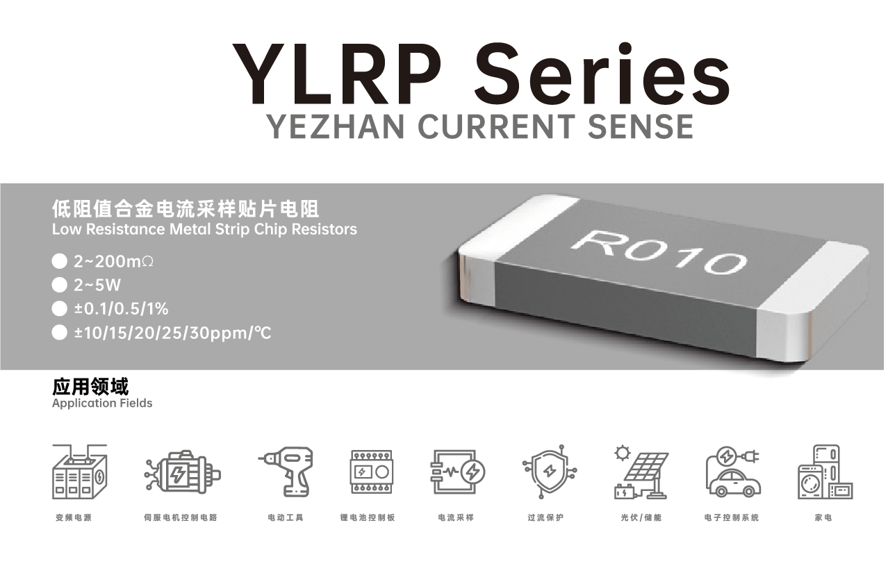

YLRP series alloy chip resistors provide precise current sensing with low resistance (2-200mΩ), low TCR, and high power rating up to 5W. Ideal for demanding automotive and industrial applications requiring stability and reliability under harsh conditions.
Designed for automotive electronics, these AEC-Q200 qualified resistors undergo rigorous testing including ESD, thermal shock, and humidity resistance. Their robust construction ensures dependable performance in power management, motor drives, and battery systems.
Offering high precision (±0.1%) and excellent TCR characteristics, these resistors are engineered for accurate current measurement in power supplies, inverters, and industrial controls. Electron-beam welded construction guarantees long-term stability and durability.
Featuring high power density in compact sizes like 2512 and 3637, these resistors deliver up to 5W performance for space-constrained designs in telecom, energy management, and automotive electronics, supporting automated assembly with tape-and-reel packaging.
With a wide resistance range from 2mΩ to 200mΩ and multiple TCR/tolerance options, this versatile series suits diverse needs from consumer electronics to renewable energy systems, ensuring stable operation across a -65°C to 170°C temperature range.
APPROVAL SHEET
YLRP SERIES
Low Resistance Metal Strip Chip Resistors
Version | Date | Description of amendment | Draft | Checked |
A1.0 | 03-Aug-2022 | First edition release | 罗国涛 | 胡紫阳 |
A1.1 | 11-Jan-2023 | modify durability test limits | 罗国涛 | 胡紫阳 |
A1.2 | 03-Mar-2023 | update pulse capability curve | 罗国涛 | 胡紫阳 |
A1.3 | 11-May-2023 | Change the product's resistance range and power description | 罗国涛 | 胡紫阳 |
A1.4 | 24-May-2024 | Update the resistance range corresponding to product accuracy and the tape size parameters | 罗国涛 | 胡紫阳 |
1.Product Description
Product name:YLRP series
Description:YLRP series alloy chip resistors provide precise current sensing with low TCR and high power, ideal for automotive and industrial applications.
1.1 Part Number Explanation
The part number of the high power precision resistor is identified by the type name, power, tolerance, temperature coefficient, size and resistance value.
Example: YLRP12-3-10F-L
Type | Size | Power | Resistance | Tolerance | TCR |
YLRP | 12=2512 17=2817 28=2728 37=3637 | 2=2W 3=3W 5=5W | 10=10mΩ | B=±0.1% D=±0.5% F=±1% | E=-50~0 G=-10~0 H=0~10 L=±10 M=±15 P=±20 N=±25 Q=±30 |
(1) Type name: YLRP series
(2) Size:12=2512;17=2817; 28=2728;37=3637
(3) Power Rating:2=2W;3=3W; 5=5W
(4) Resistance:10=10mΩ
(5) Tolerance:B=±1.0%;D=±0.5%;F=±1%
(6) TCR:E=-50~0;G=-10~0;H=0~10;L=±10;M=±15;P=±20;N=±25;Q=±30
1.2 Products & Recommend Pad Dimension
 Unit/mm
Type | Resistance | W±0.2 | C±0.2 | A±0.2 | D±0.1 | L | a | c |
YLRP12 | 2~200mΩ | 6.35 | 3.2 | 0.9 | 0.8 | 4.1 | 2.1 | 4 |
YLRP17 | 4~200mΩ | 7.1 | 4.3 | 1.2 | 0.8 | 3.5 | 2.7 | 5.2 |
YLRP37 | 2~200mΩ | 9.14 | 9.4 | 2.2 | 0.8 | 4.5 | 3.0 | 9.9 |
YLRP28 | 3~200mΩ | 6.8 | 7.2 | 1.2 | 0.8 | 4.5 | 3.0 | 7.8 |
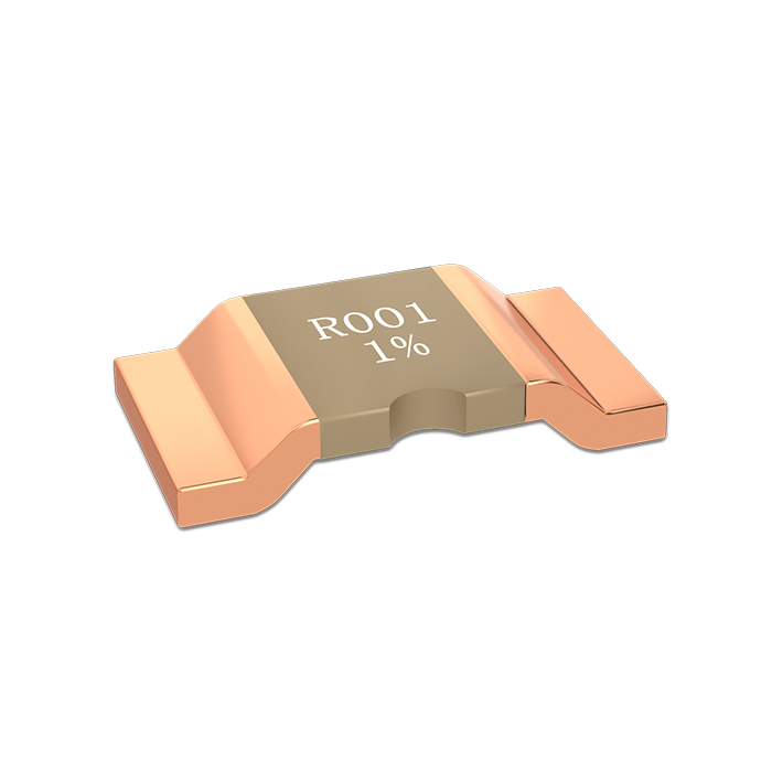
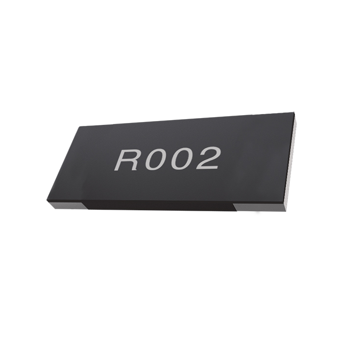
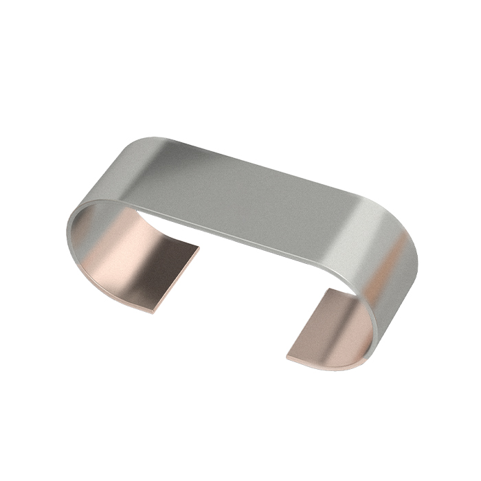
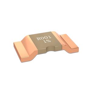
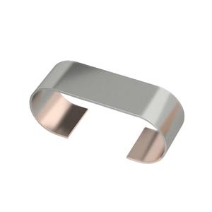
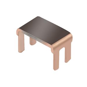
1.3 Item Construction
Electron-beam welded constructions

2. Standard Electrical Specifications
Type | Size | Rated Power (W) | Material | Resistance | Resistance Tolerance (%) | TCR① (ppm/℃) | Operating Temperature (℃) |
P70℃ | |||||||
YLRP | 2512 | 3 | Manganin | 2~4 | ±0.5% ±1% | ±25 | -65℃~170℃ |
Karma | 5~19 | E:-50~0 G:-10~0 H:0~10 L:±10 M:±15 P:±20 N:±25 Q:±30 | |||||
2 | 20~50 *51~100 | ±0.1% ±0.5% ±1% | |||||
*101~200 | |||||||
2817 | 5 | 4~19 | ±0.5% ±1% | ||||
20~50 *51~100 | ±0.1% ±0.5% ±1% | ||||||
3 | *101~200 | ||||||
2728 | 5 | 3-19 | ±0.5% ±1% | ||||
20~50 *51~150 | ±0.1% ±0.5% ±1% | ||||||
3 | *151~200 | ||||||
3637 | 5 | 2-19 | ±0.5% ±1% | ||||
20~50 *51~150 | ±0.1% ±0.5% ±1% | ||||||
3 | *151~200 |
l Short Time Overload were tested with 2.5×Rated power for 10 s
① TCR(ppm/℃):Test was conducted from 20℃ to 120℃ while 20℃ worked as the reference.
3. Endurance Test
Items | Additional Requirements | Reference | Limits |
Temperature Cycling | 1000 Cycles (-55℃ to +150℃) | JESD22Method JA-104 | ±0.3% |
ESD Test | 1) Direct Contact (DC): ±6kV; 2) Air Discharge (AD): ±12kV, ±16kV, ±25kV; | AEC-Q200 REV D June 1 | ±0.5% |
High Temperature Exposure | 1000hrs.@T=170℃.Unpowered. | MIL-STD-202Method 108 | ±0.3% |
Moisture Resistance | t=24hrs/cycle.Note: Steps 7a & 7b not required. Unpowered. | MIL-STD-202Method 106 | ±0.1% |
Biased Humidity | 1000hrs 85℃/85%RH。Note: Specified conditions:10% of operating power. | MIL-STD-202Method 103 | ±0.2% |
Operational Life | Condition D Steady State TA=125℃ at rated power. | MIL-STD-202Method 108 | ±0.5% |
Thermal Shock | 1000X(-55°C to +150°C) | MIL-STD-202Method107G | ±0.3% |
Solderability | 235℃±5℃,2s±0.5s | J-STD-202 | 95% Coverage Minimum |
Resistance to Soldering Heat | 260℃±5℃,10s±1s | MIL-STD-202Method 210 | ±0.3% |
Short Time Overload | 5×Rated power for 5 s * 2.5×Rated power for 10 s | MIL-STD-202Method 201 | ±0.5% |
Shock | 100g , 6ms , Orientation & Shock time: ±X, ±Y, ±Z; 3 times each orientation, total 18 times. | MIL-STD-202 Method 213 | ±0.1% |
Vibration | 5 g's for 20 min, 12 cycles each of 3 orientations. Note: Use 8"X5" PCB .031" thick 7 secure points on one long side and 2 secure points at corners of opposite sides. Parts mounted within 2" from any secure point. Test from 10-2000 Hz. | MIL-STD-202Method204 | ±0.2% |
4.Solder Reflow Temperature Condition

5.Power Derating Curve

6. Pulse Capability Curve


7.Pulse Capability Curve


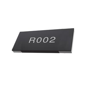
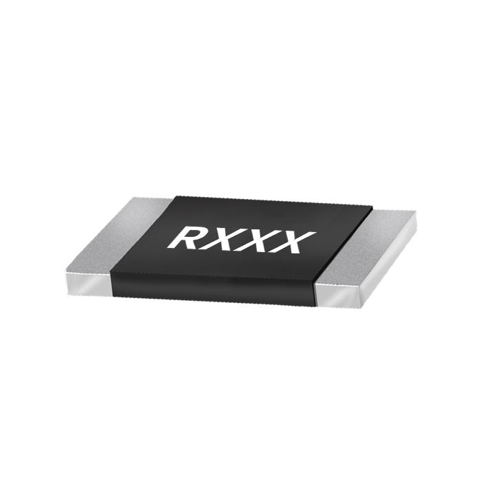
8.Marking
Laser Marking:
· All the products marking are 4 digits. ‘R’ designates the decimal location in ohms E.g.,
· 3mΩ= R003; 100mΩ=R100;1.5mΩ=1m50
· Laser marking is default. If need white printed marking, pls contact Yezhan sales team.
9. Packing
Storage Conditions:Temperature:5℃~35℃, Humidity:40%~75%
Packing Type:Bulk or Embossed Plastic Tape

Unit/mm
Type | A± 0.2 | B± 0.2 | W± 0.3 | F± 0.1 | E± 0.1 | P1± 0.1 | P2± 0.1 | P0± 0.1 | D0± 0.1 | t± 0.2 | Qty /reel |
YLRP 12 | 3.45 | 6.65 | 12 | 5.5 | 1.75 | 4 | 2 | 4 | Φ1.5 | 1.15 | 3000 |
YLRP 17 | 4.5 | 7.4 | 16 | 7.5 | 1.75 | 8 | 2 | 4 | Φ1.5 | 1.00 | 1500 |
YLRP 37 | 9.8 | 9.5 | 16 | 7.5 | 1.75 | 16 | 2 | 4 | Φ1.5 | 1.18 | 3000 |
YLRP 28 | 7.7 | 7.1 | 16 | 7.5 | 1.75 | 12 | 2 | 4 | Φ1.5 | 1.30 | 1000 |
10.  Reel & Tape Specifications
Unit/mm
Type | A±2 | N±1 | W1±1 |
YLRP12 | 178 | 60 | 12 |
YLRP17 | |||
YLRP28 | 330 | 100 | 24 |
YLRP37 |
This document is a product specification. Contents are subject to change without notice.
© 2026 THUNDER PRECISION RESISTOR CO.,LTD. All Rights Reserved.