YLRY-2010 SERIES


The YLRY-2010 series alloy chip resistors offer precise current sensing with low resistance (2–100mΩ) and stable ±50ppm TCR, suitable for automotive and industrial control systems. Available in 1W and 1.5W ratings with both standard and big terminal options.
Designed with electron-beam welded construction, these 2010-size resistors ensure high reliability and excellent thermal performance. They support tight tolerances from ±0.5% to ±5%, making them ideal for power management and sensing applications.
Featuring a big terminal version (YLRY10-K) for very low resistance (2–3mΩ), this series enhances current carrying capacity and solder joint reliability. Suitable for motor drives, battery monitoring, and compact power modules where space and performance are critical.
These resistors operate across a wide temperature range from -55°C to 170°C, meeting automotive-grade environmental requirements. Offered in tape-and-reel packaging, they support automated assembly for high-volume manufacturing.
With its compact 2010 footprint and robust performance, the YLRY series is ideal for modern electronic designs requiring reliable current detection in limited space, such as consumer electronics, IoT devices, and industrial automation systems.
APPROVAL SHEET
YLRY-2010 SERIES
Low Resistance Metal Strip Chip Resistors
Version | Date | Description of amendment | Draft | Checked |
A1.0 | 06-Jun-2025 | First edition release | 黄文强 | 王磊 |
1.Product Description
Product name:YLRY-2010 series
Description:YLRY-2010 series alloy chip resistors provide precise current sensing with low TCR and high power, ideal for automotive and industrial applications.
1.1 Part Number Explanation
The part number of the high power precision resistor is identified by the type name, power, Terminal Size,tolerance, size and resistance value.
Example: YLRY10-1A-2F-K
Type | Size | Power | Resistance | Tolerance | Terminal Size |
YLRY | 10=2010 | 1=1W 1A=1.5W | 2= 2mΩ 10=10mΩ |
D=±0.5% F=±1% G=±2% J=±5% | (Blank)= Standard Terminal K= Big Terminal
|
(1) Type name: YLRY series
(2) Size:10=2010;
(3) Power Rating:1=1W;1A=1.5W
(4) Resistance:2=2mΩ;10=10mΩ
(5) Tolerance:D=±0.5%;F=±1%;G=±2%;J=±5%
(6) Terminal Size:(Blank)=Standard Terminal;K=Big Terminal
1.2 Products & Recommend Pad Dimension

Unit/mm
Type | Resistance | W±0.2 | C±0.2 | A±0.2 | D±0.2 | L | a | c |
YLRY10 | 4~100mΩ | 5.0 | 2.5 | 0.6 | 0.6 | 3.5 | 1.5 | 3.4 |
YLRY10-K | 2~3mΩ | 1.5 | 2.0 | 3.5 |
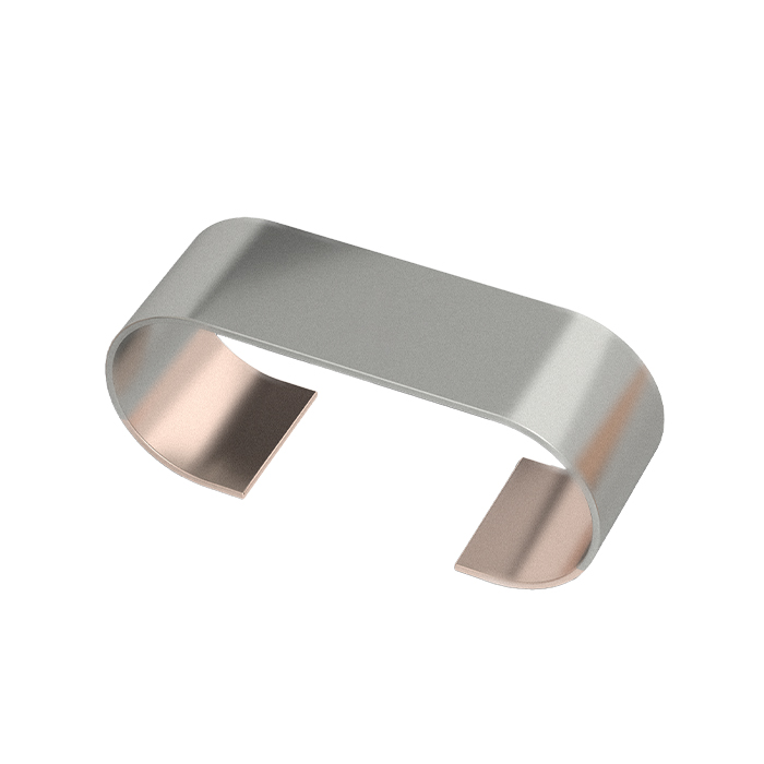
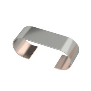
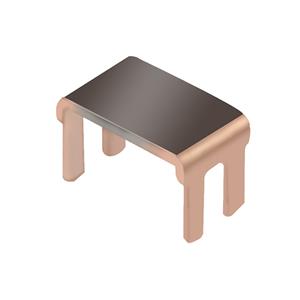
1.3 Item Construction
Electron-beam welded constructions

2. Standard Electrical Specifications
Type | Rated Power (W) | Resistance | Resistance Tolerance (%) | TCR① (ppm/℃) | Operating Temperature (℃) |
P70℃ | |||||
YLRY10 | 1 | 4~100 | D: ±0.5% F:±1% G:±2% J:±5% | ±50 | -55℃~170℃
|
YLRY10-K
| 1.5 | 2~3 |
① TCR(ppm/℃):Test was conducted from 20℃ to 120℃ while 20℃ worked as the reference.
3. Endurance Test
Items | Test Method (Refer to IEC 60115,60068;JIS-C 5201-1)
| Specifications and Requirements |
Temperature coefficient (TCR) Short Time Overload | Resistance values were measured at 25℃(T1, R1) and 125℃(T2, R2), and TCR was calculated as (R2-R1)/ (R1 (T2-T1)) *10^6 5 times rated power, maintain 5s | Refer to TCR specifications for physical features △R≤ ±(1%+0.05mΩ) |
Insulation resistance | Apply 100V±15V DC voltage between electrode and substrate, hold for 60 seconds, then measure insulation resistance | > 100 MΩ |
Withstand voltage | An alternating current with an effective value of the maximum overload voltage is applied between the electrode and the substrate at a rate of approximately 100V/S, maintaining 60±5s | No breakdown or arc |
solderability | 245℃±5℃ tin tank, hold 2s±0.5s | At least 95% of surface area of electrode shall be covered with new solder |
Resistance to Soldering Heat | 270℃±5℃ tin tank, hold for 10s±1s | △R≤± (0.5%+0.05mΩ),no visible damage |
Bending test | Bending distance 2mm, hold time 60s±5s | △R≤±(0.5%+0.05mΩ)no mechanical damage |
Solvent resistance | Isopropanol (IPA) at 23℃±5℃ for 10 hours | No obvious damage to appearance |
High Temperature Exposure | 170℃±2℃, 1000H, stand for 1H, test the resistance value | △R ≤± (1.0%+0.05mΩ) |
Low Temperature Exposure | -55℃±2℃, 1000H, stand for 1H, test the resistance value | △R ≤± (0.5%+0.05mΩ) |
Rapid change of Temperature | -55℃ 30 minutes ~ normal temperature 5 minutes ~155℃ 30 minutes, 1000 cycles | △ R ≤± (0.5%+0.05mΩ) |
Load Life | 70℃±2℃, 1000 hours, rated power, 1.5 hours on / 0.5 hours off | △R ≤± (1.0%+0.05mΩ) |
Moisture with Load | 85℃±2℃, 85%±3%RH, 1000 hours, rated power, 1.5 hours on / 0.5 hours off | △R≤± (1.0%+0.05mΩ) |
4.Solder Reflow Temperature Condition

5.Power Derating Curve

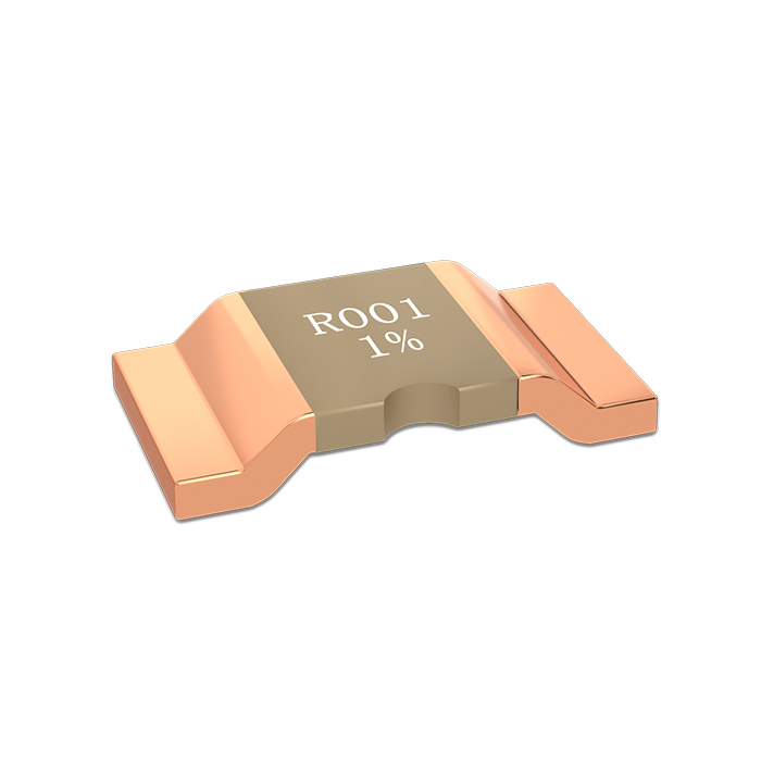
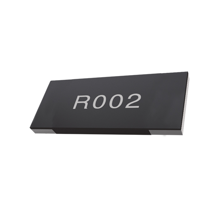
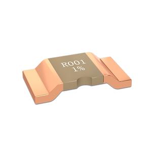
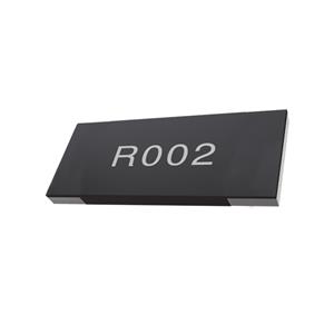
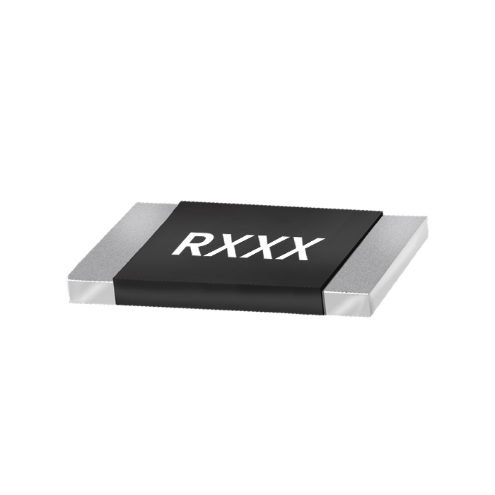
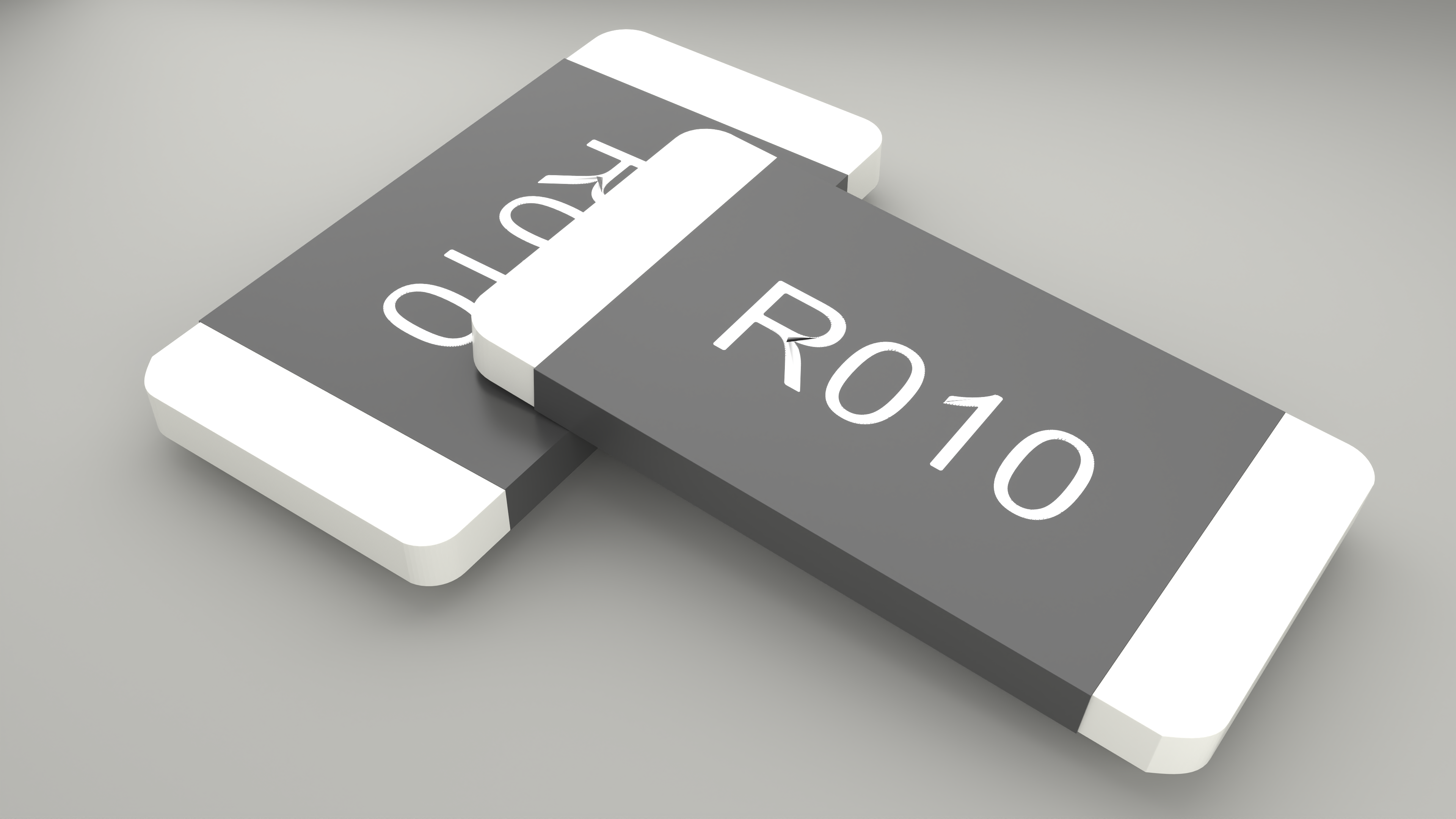
6.Marking
White Printed Marking:
· All the products marking are 3 or 4 digits. ‘R’ designates the decimal location in ohms
E.g., :
· 0= 0mΩ jumper; 5mΩ=R005; 50mΩ=R050
7.Packing
Storage Conditions: Storage Conditions: Temperature:5℃~35℃, Humidity:40%~75%
Storage life: 1 year;
Packing Type:Embossed Plastic Tape

Unit/mm
Type | A± 0.15 | B± 0.1 | W± 0.2 | F± 0.05 | E± 0.1 | P1± 0.1 | P2± 0.05 | P0± 0.05 | D0± 0.1 | t± 0.1 | Qty /reel |
YLRY 10 | 2.8 | 5.3 | 12 | 5.5 | 1.75 | 4 | 2 | 4 | Φ1.5 | 0.85 | 4000 |
YLRY 10-K | 2.8 | 5.3 | 12 | 5.5 | 1.75 | 4 | 2 | 4 | Φ1.5 | 0.85 | 4000 |
 8.Reel & Tape Specifications
Unit/mm
Type | A | N | W1 |
YLRY10 | 178±2 | 60±1 | 13.3±0.5 |
YLRY10-K | 178±2 | 60±1 | 13.3±0.5 |
This document is a product specification. Contents are subject to change without notice.
© 2026 THUNDER PRECISION RESISTOR CO.,LTD. All Rights Reserved.